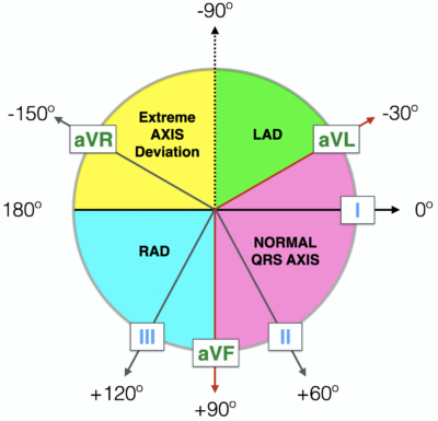
- Normal Axis = QRS axis between -30° and +90°.
- Left Axis Deviation = QRS axis less than -30°.
- Right Axis Deviation = QRS axis greater than +90°.
- Extreme Axis Deviation = QRS axis between -90° and 180° (= “Northwest Axis” = “No Mans Land”).

Methods of ECG Axis Interpretation
Method 1: The Quadrant Method
The most efficient way to estimate axis is to look at LEAD I and LEAD aVF.
Examine the QRS complex in each lead and determine if it is Positive, Isoelectric (Equiphasic) or Negative.

Method 2. Three Lead analysis – (Lead I, Lead II and aVF)
Possible LAD can be further evaluated using Lead II.

Now lets go to methods which allows more precise estimation of QRS axis
Method 3. The Isoelectric Lead(Grant method)

- If the QRS is POSITIVE in any given lead, the axis points in roughly the same direction as this lead.
- If the QRS is NEGATIVE in any given lead, the axis points in roughly the opposite direction to this lead.
- If the QRS is ISOELECTRIC (equiphasic) in any given lead (positive deflection = negative deflection), the axis is at 90° to this lead.
(i). Find the isoelectric lead. The isoelectric (equiphasic) lead is the frontal lead with zero net amplitude. This can be either:
- A biphasic QRS where R wave height = Q or S wave depth.
- A flat-line QRS with no discernible features.
(ii). Find the positive leads.
(iii). Calculate the QRS axis.The QRS axis is at 90° to the isoelectric lead, pointing in the direction of the positive leads.

Lead I and aVF are postive and so axis will be between 0 and 90 degrees.
Lead aVL is the most isoelectric
Lead II is perpendicular to lead aVL
As lead II is positive axis will be around +60 degrees.

Lead I is negative and Lead aVF is positive and axis will be RAD ie between +90 to +180 degrees.
Lead II is most isoelectric
Lead aVL is perpendicular to it and so axis will be either +150 degrees or – 30 degrees
So axis will be RAD ie 150 degrees.

Lead I is positive and Lead aVF is negative and axis will be LAD ie between 0 to -90 degrees.
Lead II is most isoelectric
Lead aVL is perpendicular to it and so axis will be either +150 degrees or – 30 degrees
So axis will be LAD ie – 30 degrees.
Now lets try to be further precise…..
Method 4.
Again use lead I and aVF
See the net deflection in both leads
Plot the points in Einthoven triangle and draw a tangential line to both points
The intersection point is the net axis.

- The deflection of the QRS complex in I is about 7 squares up and 3 square down.
- The NET DEFLECTION = +4 squares.
- The deflection of the QRS complex in aVF is about 16 squares up and 1 square down.
- The NET DEFLECTION = +15 squares.

At the intersection of these two lines, in green, we see, the axis is about +75°.
Now lets try to be further precise……
Method 5:The Star Method of Axis Calculation

Example 1

Example 2

Example 3

Example 4

Example 5

Now lets try to be perfectionist….
Method 6:
To determine the electrical axis using the area or amplitude and direction of the Electrocardiographic deflections in any two leads that are perpendicular to each other. This equation is based on the determination of the trigonometric tangent of an angle . The equation states:

G is the net deflection in the lead with the greater deflection and s is the net deflection in the lead with the smaller deflection. In order to derive the axis, the angle thus calculated is algebraically added or subtracted from the lead with the greater deflection depending on the location of the angle relative to 0° The direction of the deflections of (G) and (s) (i.e., positive or negative) is used to determine the quadrant where the angle is located.

Okamoto et al. reported that the mean frontal plane axis may vary up to +35° in an individual subject when only one lead combination is used, and they suggested the use of an average of several lead combinations when an accurate measurement is desired. It should be pointed out that the voltage in leads aVR, aVL, and aVF is only 87 % of the actual vector compared to 100% in leads I, II and III. Therefore, when comparing leads I, II and III to leads aVR, aVL, and aVF, the amplitude of the latter should be multiplied by 1.15 for greater accuracy.
Causes of Axis deviation
Causes of Left Axis Deviation include:
- Normal variation (physiologic, often age-related change)
- Left ventricular hypertrophy
- Conduction defects: left bundle branch block, left anterior fascicular block
- Inferior wall myocardial infarction
- Preexcitation syndromes (e.g., Wolff-Parkinson-White syndrome)
- Ventricular ectopic rhythms (e.g., ventricular tachycardia)
- Congenital heart disease (e.g., primum atrial septal defect, endocardial cushion defect)
- Hyperkalemia
- Emphysema
- Mechanical shift, such as with expiration or raised diaphragm (e.g., pregnancy, ascites, abdominal tumor, organomegaly)
- Pacemaker-generated rhythm or paced rhythm
Causes of Right Axis Deviation include:
- Normal variation (e.g., children, young adults)
- Limb-lead reversal (left- and right-arm electrodes)
- Right ventricular overload syndromes (acute or chronic)
- Right ventricular hypertrophy
- Conduction defects: left posterior fascicular block, right bundle branch block
- Lateral wall myocardial infarction
- Preexcitation syndromes (e.g., Wolff-Parkinson-White syndrome)
- Ventricular ectopic rhythms (e.g., ventricular tachycardia)
- Congenital heart disease (e.g., secundum atrial septal defect)
- Dextrocardia
- Left pneumothorax
- Mechanical shift, such as with inspiration or emphysema
- Conditions that cause right ventricular strain (e.g., pulmonary embolism, pulmonary stenosis, pulmonary hypertension, chronic lung disease, and resultant cor pulmonale)